-
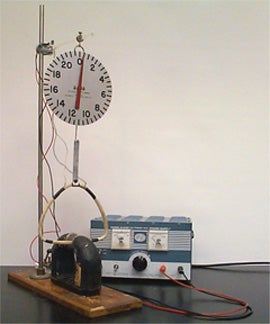
A few loops or wire shaped as a triangle hang from a large spring balance. The base of the triangular loops are placed crossing the strong magnetic field of a horse-shoe magnet. A DC power supply is connected to the triangular loops (a lecture ammeter ca also be added to the circuit). The demonstration shows that the force on a current-carrying wire in a given magnetic field varies with the current’s magnitude and direction. A switch added to the circuit shows that the direction of the force on the loops change when the direction of the current changes.
-
A long copper wire is suspended vertically by rubber bands in a tall stand (rubber bands hold the wire on both ends). The wire is connected to both poles of a DC power supply. A support at mid-height on the stand holds a U-shaped magnet, such that the wire is perpendicular to the magnetic fields of force. When a direct current moves up or down the wire, it deflects to the sides, depending on the magnet’s poles orientation. The wire’s deflection is about 2 cm to each side.
NOTE: This demonstration produces a small effect that makes it difficult for students to see the effect clearly.
-
This demo shows the basic principles of electric motors. It demonstrates the conversion of the electrical energy into rotary motion as well as the production of electrical energy from rotary motion. It consists of an armature mounted between the ends of two permanent bar magnets. The electric motor is about 40cm high, 50cm long and 15cm wide. It has a simple design and bright colors for an effective and clear demonstration.
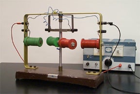
NOTE: Power supply connects to the lower terminal on the each side; red coil to + and green coil to – terminal respectively.
-
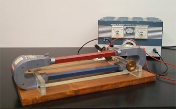
Two parallel conducting rails about 30 cm long are fastened onto a board. A conducting axle-and-wheels assembly is free to roll along the rails. The rails are placed in a strong vertical magnetic field and connected to a battery. When a current flows, the axle-and-wheels experiences a force and rolls. If the direction of the current is reversed, the axle-and-wheels rolls in the opposite direction.
-
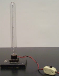
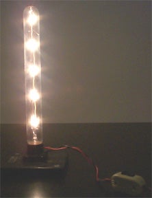
A bar magnet deflects the large curly filament of a light bulb connected to a DC power supply. If the bulb is connected to an AC voltage, the filament vibrates strongly.
-
An U-shaped wire is set swinging between the poles of a strong horse-shoe magnet. The swing is connected to the poles of a 12 V battery. When the current is allowed to pass through the wire, it jumps out of the region between the poles. You can use a switch or just keep the circuit open and touch each pole to show the effect.
NOTE: Don’t apply more than 2 Volts.
-
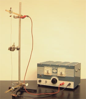
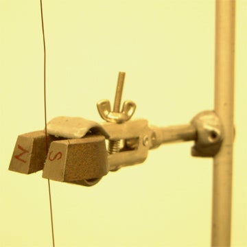
The purpose of this experiment is to measure the Lorentz force on a current-carrying copper wire subjected to a static magnetic field. The current-carrying wire is positioned horizontally and suspended by two vertical wires. The vertical poles attached to the apparatus above and below the horizontal wire provide the static magnetic field. Once the DC voltage is applied, the horizontal wire will project outwards away from the magnetic field due to the Lorentz force. The magnitude of the Lorentz force is proportional to the angle of deflection and therefore can be examined as a function of applied voltage or strength of the static magnetic field. In order to vary the magnetic field strength simply twist the vertical poles until the desire position is reached. High voltage is not required, approximately 0.1-0.3V is sufficient. For enhanced swinging apply voltage quickly and/or increase static magnetic field by adding bar magnets to vertical poles.
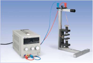
Click here to see a video of this demo.
-
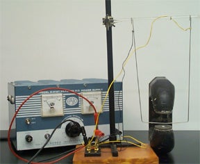
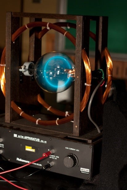
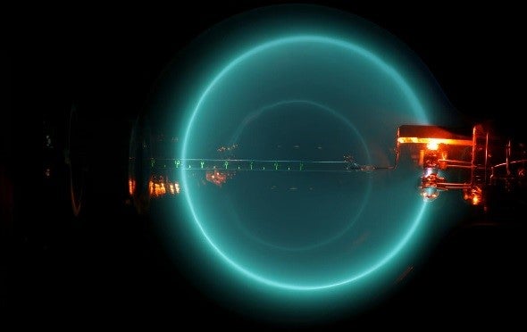
This apparatus allows students to clearly observe the effects of electric and magnetic fields on an electron stream. A horizontal beam of electrons perpendicular to the magnetic field is deflected into a circular path. It displays a brightly colored glowing beam. The apparatus allows one to measure the diameter of the circular path corresponding to the applied voltage and deflecting field. The large orbital electron path is circular and Helmholtz coils are integrated. The beam has a built-in engraved glass rod with a scale along the central axis.
Specifications:
• Vacuum Tube:
– 130mm diameter
– Helium gas
– Integrated phosphor scale
• Helmholtz Coil:
– 300mm diameter
– 1mm wire 130 turns
– Two parallel mounted coils with variable resistors to adjust current
• Anode: 200-500V
• Heater: 6.3V/1A
• Helmholtz coil: 12V DC/2A
Dimensions:
370mm x 255mm x 388mm (L x W x H)
Current in a Magnetic Field
Contact our lab
Visit Us
USC Physics Lecture Support Lab SLH (Stauffer Lecture Hall) – 104
Department of Physics and Astronomy
University of Southern California
Los Angeles
Questions or Comments
If you have questions or comments e-mail us or call at phone number below.