C.1 – Parallel Plate Capacitors
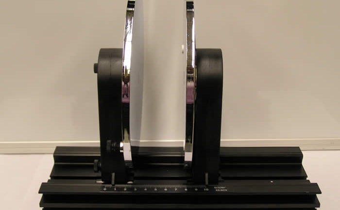
A capacitor has large parallel plates (22 cm in diameter) that can slide on a board, thus varying the distance between them. The set-up in the figure is used to show how the voltage across the capacitor varies with the distance between the plates. The capacitor is connected to an electrometer, and completely discharged. It is then disconnected and charged to 25 volts with a DC power supply. Touch each plate with each of the power supply’s electrodes for a few seconds. Now re-connect the electrometer and vary the distance between the plates. Observe the corresponding variation on the electrometer readings. The electrometer is connected to a projection meter so that the voltage variations can be read by all students. For another demonstration using the same set-up, push the glass plate between the capacitor’s plates. Discharge the capacitor and the electrometer, while they are still connected, using the ground lead of the electrometer. As before, disconnect the electrometer and charge the capacitor to about 25 V. Re-connect the electrometer. Now, check the readings and pull the glass plate away from the capacitor’s plates while observing the voltage increase.