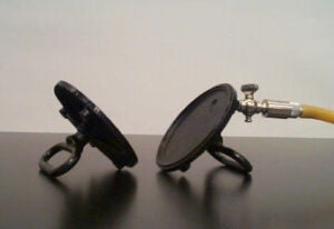
F.1(1) – Magdeburg Plates
Two plates, 12 cm in diameter, having grip handles for pulling and a metal nipple in one of the plates. A rubber hose connects it to a vacuum pump. Check the valve on the nipple for open and turn on the pump. After a minute or so, close the valve and turn the pump off. The hose can be removed. This demonstrates the effect of external pressure by attempting to pull the plates apart. When the stopcock is opened, the two plates fall apart.
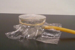
F.1(2) – Bubble Burster
A glass vessel (7.5 cm x 10.5 cm) with a lateral outlet to fit a rubber hose is connected to a vacuum pump. A cellophane sheet is used as a diaphragm, sealing the top of the vessel. When the pump is turned on and the vessel evacuated, the membrane implodes demonstrating the effects of external pressure .
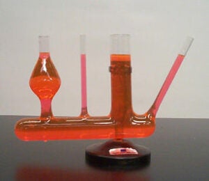
F.1(3) – Constant Level Tubes
The apparatus consists of four glass tubes of various shapes manifolded together. The container is half-filled with water. A dye is used to color the water to aid visibility at a distance. It shows that a liquid in connecting vessels of different shapes stands at the same level.
F.1(4) – Water Pumps
Models of a lift pump and a force pump are available.
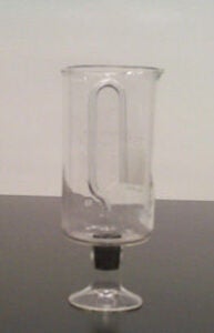
F.1(5) – Intermittent Siphon
A glass cup has an open bottom closed by a stopper with a U-tube attached. Pour water into the cup. When water reaches the top of the inverted U-tube, a siphon begins which drains the water until the end of the U-tube is exposed.
When the cup is filled, water is forced up the inverted U-tube so that it maintains the same level as the water in the cup. As the water level reaches the top of the U-tube, it begins to fall through the tube. As the water falls, it creates a vacuum in the tube, which causes more water to be forced into the tube from the container. The vacuum created causes the atmospheric pressure to push the water out of the cup through the U-tube. Water will be falling out of the tube, creating a vacuum, causing more water to be forced into the tube, until the water level in the container falls below the level of the end of the tube in the container. It models the intermittent flow of some natural springs. This cup is known as a Tantalus cup after the legendary king of Lydia, Tantalus.
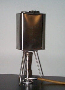
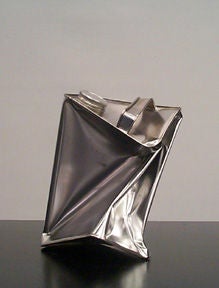
F.1(6) – Metal Can
It is a light metal can, about 20 cm x 10 cm x 25 cm, with a threaded lid. A little water is poured in the can and it is heated over a flame. As the water boils and the can is filled with steam, set it aside and close the lid, sealing it tightly. After a while, as the steam begins to condense, the atmospheric pressure crushes the can. The same principle can be applied using a soda can; by boiling water in an emptied soda can and immediately turning it upside down in a cold water-filled container, the can will crumple and collapse.
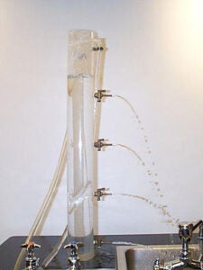
F.1(7) – Torricelli’s Law
The equipment used is a tall, clear plastic, cylindrical tank with four orifices spaced equidistantly. Each orifice has a small metallic faucet. There are also two overflow openings, with a rubber hose connected to each one. Fill the tank with water, and with the rubber hose, maintain an even head of water at all times once the faucets are opened. The water should never sink below the overflow tube. As the water flows through all the orifices, bottom stream reaches further than all others. The velocity of each of the streams at the orifice, obtained by applying Bernoulli’s Law, is such that the lowest orifice has the greatest velocity.
F.1(8) – Lung Demonstration Apparatus
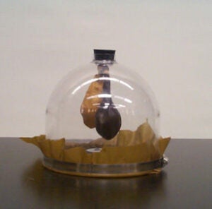
It shows how the lungs are emptied and filled with air by the relaxation and contraction of the diaphragm muscle. The chest cavity is simulated by a half-gallon bell jar closed on top by a rubber stopper and stout rubber sheet which acts as the diaphragm. The rubber stopper has a Y-tube through it with two balloons attached to it, simulating the lungs. Pull the knob in the center of the rubber sheet up and down to see the balloons (lungs) getting emptied and filled with air.
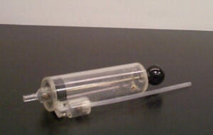
F.1(9) – Cloud Formation
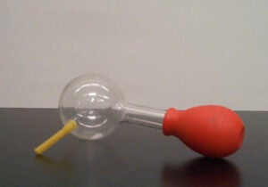
It demonstrates atmospheric conditions in the upper air during cloud formation. A glass spherical bottle has a side opening which is fitted with a rubber hose and clamp. A large rubber bulb is fitted on the tube’s neck. Fill the rubber ball with very little water. Compress the bulb while the side tube is open, forcing air from the flask. Fill the glass bulb with smoke by holding the inlet near a smoking match (or touch paper) and releasing the rubber bulb. Close the side opening. Now, by compressing and suddenly releasing the rubber bulb, a dense cloud forms in the flask. When the pressure is lowered suddenly, the excess vapor condenses and forms tiny droplets around each particle of dust or smoke. Compress the bulb again and the cloud clears. The procedure may be repeated many times without adding more smoke.
F.1(10) – Blood Pressure Meter
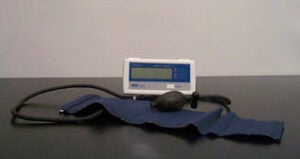
A digital, commercial meter is available to show how much someone’s blood pressure varies if measurements aren’t taken with the arm on the same level relatively to the heart.
F.1(11) – Atmospheric Pressure Demonstrator
A partial vacuum forms under the atmospheric pressure demonstrator (APD) when it is placed on a smooth, flat surface and pulled straight upward with the handle. The pressure differential that is created prevents the removal of the APD from the flat surface. A heavy board or stool can be lifted to further dramatize the force of atmospheric pressure.
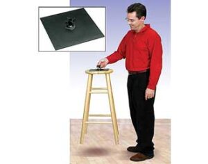
Click here to see a video of the APD in action.