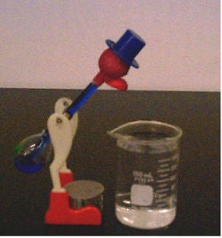
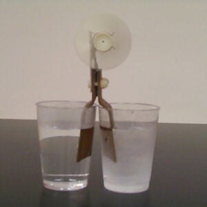
T.5(1) – Drinking Bird
A shapely glass tube is dressed-up as a bird and hangs by its “hips”, being supported half-way up its length. Cooling by evaporation, its beak draws up a colored liquid (methylene chloride) through a tube in its body. This over balances the bird so that it takes another drink. A beaker filled with water is set in front of the bird. Hold its head down, wetting the beak for a minute or so. Let it go and it will bounce back to the upright position. After a while, it will lowers its head by itself and bounce back again. And on, and on.
T.5(2) – Cory Hero’s Jet Engine
This demo operates under the same principles as the Hero’s Jet Engine demo (M.6 (5a)), but with liquid nitrogen used in the spinning container instead of water. A plastic bottle is used as the container instead of glass flask in order to avoid fracturing and breaking from thermal stress.
NOTE: Video available online.
NOTE: 48 Hour notice required for setup
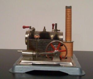
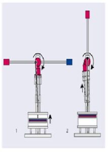
T.5(3) – Steam Engine
The steam engine runs on stream pressure made by heating water in a boiler the same way water is boiled in a tea kettle. Remove safety valve and pour water (preferably warm) into boiler until gauge glass show 1/2 to 2/3 full. Replace safety valve, steam pressure will develop after several minutes as indicated by steam appearing at the exhaust.
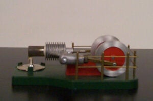
T.5(4a) – Stirling Cycle Hot-Air Engine
This 17.8 cm x 10.8 cm model will run on alcohol. The operating principle of the hot air engine is based on the Sterling cycle, with the following idealized P-V diagram.
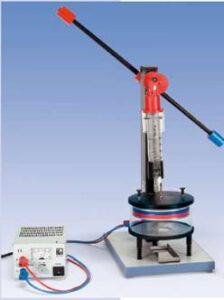
T.5(4b) Hot-Air Engine (Stirling Engine)
The Stirling Engine demonstrates a simple example of a heat engine in which during the course of a thermodynamic cycle thermal energy from a high temperature reservoir is partially converted to mechanical energy. The Stirling Engine is connected to a DC power source which electrically heats the bottom of the large cylinder. As the air in the large cylinder heats and expands, the piston retracts. Consequently, mechanical energy is transferred to the flywheel. As the piston returns to the bottom of the large cylinder, the air is displaced towards the top so that it cools. The cool air is then compressed by the large syringe due to the mechanical work provided by the flywheel. The result is a simple thermodynamic cycle of heating, expansion, cooling, and compression. For optimal results use a DC voltage of 11V and allow a few seconds for the air inside the large cylinder to heat. An initial push may be required for the heat engine to begin.
Click here to see a video of this demo.
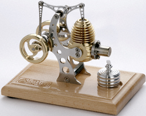
T.5(4c) – Boehm Stirling Hot-Air Engine
This Stirling engine has an overhead rocker arm and a precision crankshaft.
Base measurements: 158 x 108 x 120
Working rpm: 2000 rpm/min – 2500 rpm/min, to regulate as slowly run
Bearing application: 6 high-class ball-bearings
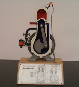
T.5(5) – Two-Stroke Engine
It is a sectional model demonstrating its action in detail. The internal parts are color-coded and on its base there is a diagram, giving names to all parts. By turning a handle, one drives the motor, lighting up a lamp in the ignition chamber each time ignition occurs. It is 38 cm high over all and powered by a 6 V power supply.
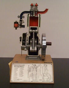
T.5(6) – Four-Stroke Engine
The Otto cycle is one of the fundamental cycles used in internal combustion engines. This model is also a sectional model showing the indicated engine’s motion. It is also driven by a handle. A lamp in the ignition chamber replaces actual ignition, lighting each time ignition would occur. A 6 V power supply powers the lamp. It is 38 cm high, mounted on a wooden base which had a diagram on the front explaining the parts.
T.5(7) – Thermoelectric Convertor
This apparatus consists of two copper stripes (4 cm wide, 12 cm high) connected to a small propeller on the top, as a wind tower. When one leg is set in ice-cold water bath and the other in a boiling water bath, the difference in temperature will run the device. If the two legs stand at the same temperature, it will not turn. The converter consists of series-connected semiconductor junctions “sandwiched” between two copper legs. The difference in temperature creates an electrical potential that powers the motor and spins the propeller. It converts thermal energy to electrical energy. It demonstrates that a temperature differential is essential for extracting usable energy; and that a process occurs naturally if energy is conserved and entropy increases.
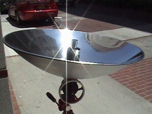
T.5(8) – Sun Runner Stirling Engine
The Sun Runner, a solar-powered Stirling Engine, offers a dramatic demonstration of energy conversion. This motor and its parabolic mirror can be attached to any conventional camera tripod. When properly aimed at the sun, the polished aluminum parabolic mirror focuses incoming solar energy on the heat cap of the engine, which is converted to rotary motion.
Click here to see a video of this demo.
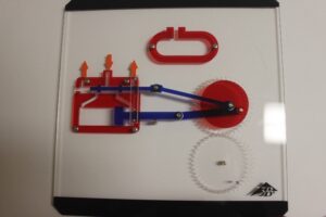
T.5(9) – Four-Stroke Engine Model
A four-stroke engine, also known as four-cycle, is an internal combustion engine in which the piston completes four separate strokes—intake, compression, power, and exhaust—during two separate revolutions of the engine’s crankshaft, and one single thermodynamic cycle. This demo displays a cut-away view of a Stirling engine, and can be shown to classes via an overhead projector.
Click here to see a video clip of this demo being used with an overhead projector.
T.5(10) – Stirling Engine Model
A stirling engine is a heat engine operating by cyclic compression and expansion of air or other gas, the working fluid, at different temperature levels such that there is a net conversion of heat energy to mechanical work. Typical of heat engines, the general cycle consists of compressing cool gas, heating the gas, expanding the hot gas, and finally cooling the gas before repeating the cycle. The efficiency of the process is narrowly restricted by the efficiency of the Carnot cycle, which depends on the temperature difference between the hot and cold reservoir. This demo displays a cut-away view of a Stirling engine, and can be shown to classes via an overhead projector.
Click here to see a video clip of this demo being used with an overhead projector.
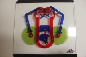
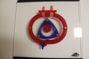
T.5(11) – Wankel Engine Model
As the rotor rotates, each side of the rotor gets closer and farther from the wall of the housing, compressing and expanding the combustion chamber similarly to the strokes of a piston in a reciprocating engine. Compared to a four-stroke piston engine, which makes one combustion stroke per cylinder for every two crankshaft rotations, each combustion in a Wankel engine generates one combustion stroke per each driveshaft rotation, which allows for higher power output in comparison. This demo displays a cut-away view of a Stirling engine, and can be shown to classes via an overhead projector.
Click here to see a video clip of this demo being used with an overhead projector.