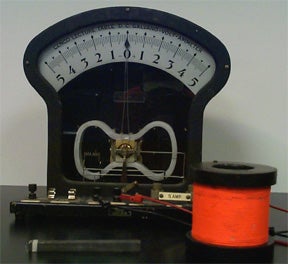
EM.2(1) – Faraday’s Electromagnetic Induction Experiment
An induction coil and lecture galvanometer are used in this demonstration. A bar magnet plunged into the coil produces an electric current in the coil, that is indicated on the galvanometer. When the magnet is removed, a current in the opposite direction is produced. The needle deflection on the galvanometer is clearly seen by the whole class.
The Faraday Experiment is now tried with a single loop instead of a coil of wire. The deflection in the galvanometer is much less in this case. It can also be done with an increasing number of loops to show its dependence on the number of loops.
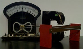
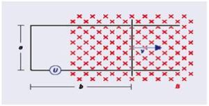
EM.2(2) – Induction Rails
Two conducting rails are connected to a lecture galvanometer. The rails are placed around the magnetic field of a large horseshoe magnet. When one slides a conducting rod quickly along the rails, cutting the magnetic field, an emf is induced. The induced emf is indicated by a deflection of the needle in the galvanometer. Move the rod in the opposite direction and the galvanometer needle will deflect in the opposite direction. The induced current is in such a direction as to produce a magnetic flux that opposes the change in the magnetic field caused by sliding the conductor.
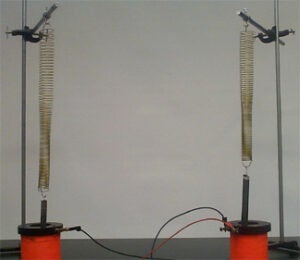
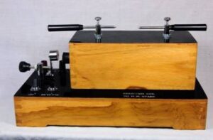
EM.2(3) – Current Coupled Coils
Two induction coils are connected by long wires and set far apart in the lecture room. Tall stands are arranged close to them so that the bar magnets on springs oscillate in them. When one magnet is set oscillating, the induced current causes the other to oscillate also.
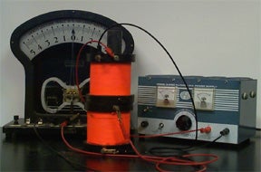
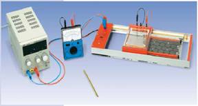
EM.2(4) – Induced Current – Two Coils
One induction coil is connected to a lecture galvanometers, as in EM.2(2) and the other to a DC power supply and a switch. One coil is set atop the other but they are not connected. Turn the power supply on. When the switch is opened or closed, the current induced in the other coil will be indicated at the galvanometer.
An iron core set through both coils will enhance the effect.
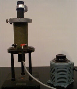
EM.2(5) – Jumping Ring Experiment
An induction coil with an extra long iron core is supported vertically with part of the iron core pushed up. A solid metal ring is set around the iron core, over the coil. The induction coil is connected to an alternating power source. When the alternating current is applied to the coil, the metal ring is thrown upwards into the air. Try it with a split ring and nothing happens.
The current induced in the metal ring produces a magnetic field that opposes the field generated by the induction coil.
Click here to see a video of this demo.
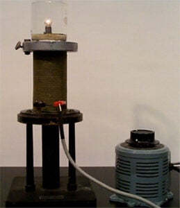
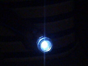
EM.2(6) – The Submerged Lamp
The same set-up of EM.2(5) is used, but now with the iron core lowered so that a beaker can be placed on top of the coil. Inside the beaker, there is a small coil of wire with a small lamp in the middle. When an alternating emf is applied to the induction coil, the small lamp will light up. Fill the beaker with water, and it lights up again with an alternating emf is applied.
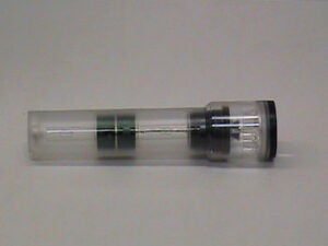
EM.2(7) – Magnetic Force Flashlight
Shaking this flashlight for 1 minute will produce 1-2 hours of light. It has two coils inside that can be easily seen by observers. This demo exhibits the principles of Lenz’s law.
EM.2(8) – Electromagnetic Damping
The induction coil is laid on its side and supported so that the iron core is horizontal. The iron core is allowed to protrude about half of its length from the coil. A support rod clamped to the induction coil’s end plate holds a copper or aluminum ring over the magnet core by a cord. The ring hangs freely about the core. The coil is connected to a 6 V battery or a DC power supply through a switch. Close the switch rapidly. The ring will be suddenly propelled outward, and then it will swing slowly back to its vertical position without oscillation. Open the switch and the ring will first swing toward the coil, and then oscillate about its free position.
When the switch is closed, the current induced in the ring creates an opposing field, which, by interaction with the field produced by the current in the induction coil, retards the motion of the ring. The energy supplied by the motion of the ring is absorbed by the induced current in the ring, thus providing an excellent demonstration of electromagnetic damping. When the switch is opened the magnetic field is nearly non-existent and no damping occurs.
A hand-cranked generator wired to a light bulb is also a useful demonstration of Lenz’s law as it can be verified by a volunteer that it is much easier to turn when there is no load in the circuit, i.e. when the light bulb is disconnected.
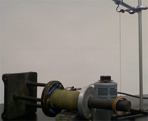
EM.2(9) – Induction Spark Coil
This experiment demonstrates electromagnetic induction: repeated breaks of the primary current induce high voltage pulses across the secondary terminals. This is visually observed through the resulting sparks between these terminals (located on top of the induction coil apparatus). The apparatus is connected to a DC power supply (voltage ~ 7V, current ~ 2A).
Turn on the apparatus, after checking that the vibrator is positioned away from the primary terminal. Slowly turn the knob to move the vibrator toward the terminal, until the former is vibrating and sparks start jumping across the secondary terminals.
EM.2(10) – Induction Tube
The purpose of this experiment is to demonstrate the realization of an induction current. An approximately three foot tube with equally spaced, tightly bound, coils is connected to an amplifier. Each set of coils is connected to the previous set, finally converging to a lead connection site. The induced current collected from the coils is sent from the lead connection site to the amplifier where the signal is manifested auditorily through three five inch speakers. The signal can be quite low, therefore it is suggested that the amplifier be set to its maximum volume.
Click here to see a video of this demo.
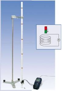
EM.2(11) – Induction Conductor Loop
The purpose of this experiment is to show a voltage (thus current) will be induced around the loop when the magnetic flux passing through the loop changed with time. The magnitude of induced voltage depends on the number of turns in the conductor loop. There are three choices in this experiment. To see the change of induced voltage, we will use a projection meter. To maximize the deflection of voltmeter, use hand to move the loop instead of use the build-in motor. (NOTE: The induced voltage produce small deflection in voltmeter, to impress student, you can switch to current mode which will maximize the deflection of projection meter).
Click here to see a video of this demo.
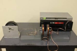
EM.2(12) – Dual Coil Inductor Radio
Using two sets of tightly wound coils, this experiment is designed to show how current/voltage can be transferred from receiver to speaker by magnetic induction. The setup consists of a receiver connected to a DVD player, which provides the music that is to be transmitted. The receiver is connected to one set of coils, set A, which provides the time dependent magnetic field necessary for magnetic induction to occur. The second set of coils, set B, is connected to a five inch speaker, where the output of the DVD player will be captured. As sets A and B are brought closer to each other the magnetic flux will increase in set B thereby increasing the strength of the output signal, the volume. The variation in signal output relative to the distance between sets A and B can be analyzed along with the effect of rotation. Relative rotation between sets A and B will change the output strength such that at 90 degrees the magnetic flux in set B will be zero, i.e. no output signal.
Click here to see a video of this demo.
EM.2(13) – Paper Cup Speaker
A speaker is a device that converts an electronic signal into sound. In this demo, an electronic signal is converted to AC current and travels through the wire from the signal source. The current loop of wire induces a magnetic field perpendicular to the wire loop. This small magnetic field interacts with a larger magnetic field generated by inserting a large permanent magnet into the speaker cup. The magnetic flux creates a disturbance, vibrations, in the medium, which generates the sound that we hear due to the presence of air.
Click here to see a video of this demo.