EM.10 – Short Wave Radio Demonstration
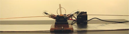
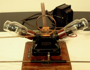
This apparatus demonstrates the fundamental principles of radio transmission antennae. It consists of an oscillator unit that drives a high-frequency oscillator loop. The frequency of the oscillation is about 94 MHz (the wavelength generated by the oscillator unit is about 3.2 m). The circuit consists of two triodes, a resistor, two large capacitors, the oscillator loop and a choke coil. The two telescoping antennas are connected to the antenna jacks at either end of the oscillator loop to form a half-wave dipole, increasing the radiating efficiency of the oscillator unit. The electromagnetic waves are picked up by a receiving antenna. With a flashlight bulb and adjustable length , it detects and “tunes in” the radio waves generated. It illustrates many aspects of dipole radiation, such as:
Polarization: no signal is picked up if the receiving antenna is perpendicular to the transmitting antenna.
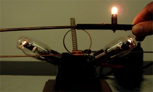
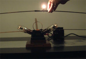
Nodes and antinodes of voltage can be detected. A two-part 1.6 m long wand with a copper band and flashlight bulbs fixed at every 20 cm detects half of the wave generated. The bulbs are bright in the center and the ones at the end do not light up. A neon light bulb touching the transmitting antenna will light up and remain so as long as the bulb is kept parallel to the transmitting antennae.