M.5(1) – Projectile Motion
-
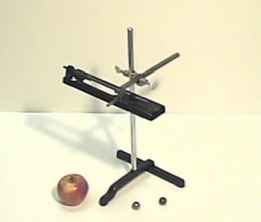
This apparatus demonstrates that the vertical and horizontal components of a projectile trajectory can be treated independently. It shows that for vertical fall, the time of fall is independent of any horizontal velocity possessed by the projectile. Two balls are released simultaneously from a platform. One is projected horizontally by a spring gun and the other is allowed to fall freely. Both reach the floor at the same time.
-
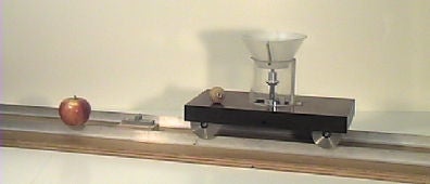
A unique wooden cart with aluminum wheels has a cone set upside down over a clever system that holds down a small ball drilled through its axis. The system is triggered, projecting the ball, when the cart runs over a small obstacle mounted in the middle of the track. The track is a wooden board supporting an aluminum rail and it is about 2 m x 30 cm. The track lies on a table and a small push is given to the cart on the track. When it passes the trigger, the ball is fired vertically. The ball undergoes both horizontal and vertical motion and lands on the cart. This demonstrates the independence of horizontal and vertical motion.
-
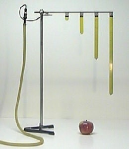
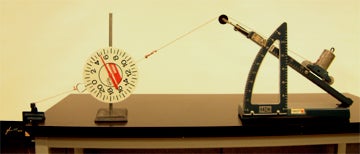
The apparatus consists of a support rod set at an angle to the stand, a water nozzle with attached tubing, and four pivoted pointers. The pointers are attached to the rod at regular intervals so that the pointer tips lie on a parabola. The tubing is attached to the water faucet; the water is started and adjusted to graze the tip of the first pointer. Remarkably, the stream is observed to graze all the other pointer tips. The result is found to be independent of the angle at which the apparatus is supported.
-
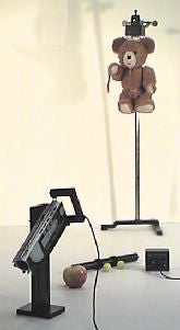
This apparatus demonstrates projectile motion. It consists of a projectile launcher mounted on a heavy stand, with a steel projectile as a bullet and a stuffed animal as a target. The barrel of the launcher is aimed directly at the target which is held by a magnet. The target is released when the steel ball passes by the nozzle of the launcher, breaking the circuit. The ball and target collide in mid-air. The projectile launcher is set on the lecture bench with the circuit breaker turned downward. To repeat the demonstration, reload the steel ball back in the projectile launcher, trying not to disturb the aim very much. Hang the target, check the aim through the eye piece, and release the launcher.
Click here to see a video of this demo.
-
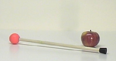
A 30 cm rod has different sized rubber balls attached at each end. The system’s center of mass is painted with fluorescent ink. Dim the lights and throw the rod from one side of the room to the other. The students will be able to observe the fluorescent dot performing a parabola. With the lights on, they can see the rotating motion of the two balls around their center of mass.
M.5(2) – Accelerated Motion
-
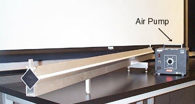
The air track can be used to demonstrate a variety of concepts such as:
- Newton’s law of motion
- Conservation of momentum in one-dimensional collisions
- Oscillation of a system of connected masses
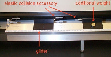
The 2 meter track is connected to the air blower at one end and has many equally spaced small holes over its length. Its accessories include 4 gliders equipped with bumper strings for elastic collisions, extra weights, connections for inelastic collisions and springs for harmonic motion demonstrations
-
A glider is connected to a hanging 5 g weight by a string, which passes over a pulley. The friction involved by the pulley and glider is negligible. The pulley’s only effect is to change the direction of the string. Allowing one to determine an expression for the acceleration of the glider in terms of Mg, Mw, and g:
a = Mw / (Mg + Mw) * g
Its accessorices include additional weights for the pulley and weight holder.
Specifications: Pulley: diameter = 4.8 cm weight = 9.4 g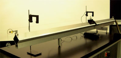
-
The set-up consists of an inclined plane with a pulley fixed on the elevated end and a half protractor in front of the plane (among others). The inclination angle can be varied from 0° to 45°. The metal cart has a small case where masses can be added and is tied to a string that goes through the pulley and hangs vertically. Different weights can be hanged to change the cart’s acceleration. In addition, a balance can be tied to the string and observed as the inclination angle is changed.
-
The air table is an ideal setting in which to demonstrate many basic physical laws that relate to forces and the transfer of energy between bodies in motion. It is a relatively friction-free surface due to a continuous stream of air which reaches the table surface through numerous regularly spaced holes.
Dimensions of table: 1.5 m x 1.5 m
Dimensions of the pucks: 7 cm and 10 cm in diameter.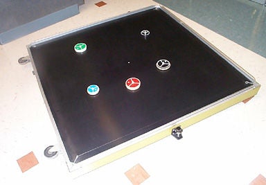
NOTE: Please allow us at least one day notice so that we can check and adjust the air table.
M.5(3) – Hovercraft
-
PASCO’S Hovercraft is designed to help students experience frictionless motion, thus better understand Newton’s Laws. Its large platform provides enough area for the rider to comfortably sit while riding. The weight limit is 250 pounds.
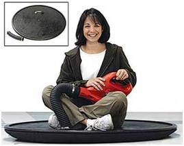
Click here to see a video of the hovercraft in use.