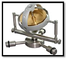
M.15(1) – Large Demonstration Gyroscope
It is about 30 cm in diameter and very heavy. It is set to rotate on a stand about 20 cm tall. A gyro-spinner (a motor) is used to achieve high rotational speeds. The wheel in rapid rotation has a large moment of inertia on account of its relatively large rim mass and high rotational velocity. Therefore, the wheel resists change from the plane in which it is rotated. One can test this by when one attempt to change the position of the gyroscope; it exercises a force against that. Large gyroscopes have been built for providing steady navigation of ships, submarines, rockets and space ships.
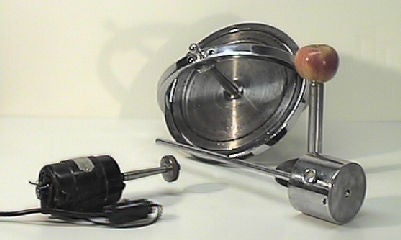
M.15(2) – Demonstration Gyroscope
This is a smaller gyroscope (15 cm in diameter, 25 cm in height) mounted on one end of a balancing rod. The rod has a moveable weight which will counterbalance the gyroscope top. It demonstrates the gyroscope’s behavior when it is counterbalanced with its spin axis parallel to the balance arm. When the top is rotating, the rod will remain horizontal regardless of the position of the weight: it will move in a horizontal circle around the stand’s axis in one direction if the weight is before the balance point in the rod, and in the opposite direction if the weight is after it.
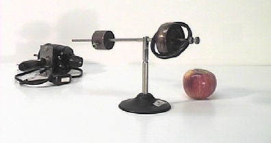
M.15(3) – Gyroscope with Gimbal Rings
A secondary ring attached to this small gyroscope gives it three degrees of freedom. It can demonstrate that the axis of the gyroscope will maintain its spin direction, no matter how you move the support.
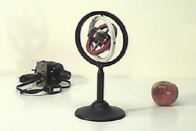
M.15(4) – Air-Bearing Gyroscope
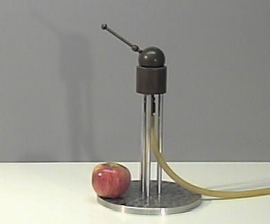
This apparatus consists of a massive metal sphere of about 5 cm in diameter resting on a spherical metallic support, of diameter slightly larger, on a 20 cm tall stand. The stand is connected to the pressured air supply. The sphere has a metal rod extending about 10 cm. When the air is turned on, it forms a thin film of air causing the sphere to float. A small motor is used to initiate rotation around the metal rod. With the sphere rotating around this axis, it shows precessional movement when the rod is tilted from the initial position.
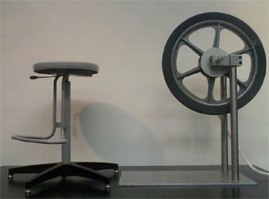
M.15(5) – Bicycle Wheel Gyroscope
M.15(5) – Bicycle Wheel Gyroscope
M.15(6) – Maxwell’s Top
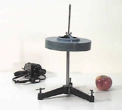
The Maxwell top is designed to illustrate conditions for gyroscopic precession. Its spindle may be adjusted so that the pivot is above, below, or coincident with the center of gravity. When above, the top precesses in one direction; when below it precesses the other way; when coincident, it fails to precess at all, but will spin steadily. The disk is about 20 cm in diameter and 3 cm thick. When the pivot is set coincident with the center of gravity and the top spun with the axis vertical, it will move along any object held against the top of the spindle
M.15(7) Powerball Gyroscope
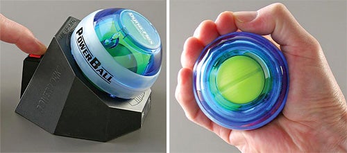
This device uses precession to increase a spinning mass’s angular speed. The powerball consists of a spinning mass whose axle’s ends are allowed to move along a groove inside the device’s outer shell. Once the inside mass is spinning, it can be made to precess along the groove by an external torque applied manually; thanks to static friction, the axle rolls inside the groove, thus spinning up the mass. One can use a speed meter to display the angular speed achieved.
Note: some practice is needed to find the proper twisting motion achieving spin-up. Also, a large enough initial spin is required (this is because the coefficient of static friction necessary to sustain rolling decreases as theangular speed increases).
M.15(8) Super Precision Gyroscope
The super precision gyroscope is made of solid brass and aluminum with a miniature high grade bearing that can run for up to 4 minutes. The electric starter spins the gyroscope to speeds of approximately 12,000rpm. There are 7 places on the frame of the gyroscope that attachments can be screwed into. Accessories are available to perform various experiments.
Click here to see a video of the Super Precision Gyroscope demo
